Flattening Drawings Automatically
Use the Flatten command to automatically flattening drawings.
You can flatten all entities of the drawing or only a specified subset. For example, the SmartSelect command lets you select sets of entities by category. Also, the command may automatically count how many entities of a particular type have been modified during the flattening process.
Note: You can interrupt the execution of the Flatten command at any point by pressing Esc.
Note: After flattening, resulting 2D entities retain their original Layers, LineStyles, and colors.
You can do the following:
- Create a 2D representation from a 3D model
When you flatten a 2D view or a 3D view of a 3D model, the command projects the specified 3D entities onto the current viewing plan, or on the XY-plan of the current coordinate system. The model view is created using 2D entities.
- Correct drawings that have unknown Z-coordinates
While working on a drawing, it might happen to have properties, such as thickness, elevation or other not representative property for a 2D entity.
 Use one of the following tools to choose a suitable 3D view and check if the drawing has Z-coordinates:
Note: Accuracy loss might occur in the following situations:
- Flattening without hidden lines
- Flattening a perspective view
Properties that may add elevation or Z coordinate to a 2D entity:
| Entity | Properties |
|---|---|
| Polyline, Hatch, Cloud | Elevation |
| Line | Start Z, End Z |
| Circle, Arc, Ellipse | Center Z |
| Spline | Fit Point Z |
| Annotative Entities | Position Z |
To flatten a drawing with unknown Z coordinates:
- Do one of the following:
- On the menu, click XtraTools > Modify > Flatten.
- On the ribbon, click XtraTools > Modify > Flatten.
- Type Flatten.
- Optionally, specify Statistics.
- Type Yes or No to enable or disable the report on modified entities.
- Optionally, specify Plane to set the projection plane.
- Specify XY to flatten entities on the XY-plane.
- Select all entities of the drawing with Z coordinate different than 0.
Alternatively, you can use the SmartSelect command to select the entities with varying Z-coordinates.
- Press Enter.
- To specify whether to remove hidden lines, type Yes or No.
The drawing is flattened. All Z coordinates are 0.
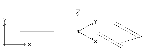
Example:
| Top view of a seemingly 2D drawing | 3D view shows entities with Z coordinate |
 |
|
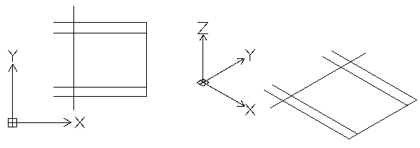
| Flattened top view | 3D view shows that all entities are in the same plane |
 |
|
To flatten a 3D view of a model:
- In the graphics area, set up a suitable 3D view. Use the Views command.
- Do one of the following:
- On the menu, click XtraTools > Modify > Flatten.
- On the ribbon, click XtraTools > Modify > Flatten.
- Type Flatten.
- Optionally, specify Statistics.
- Type Yes or No to enable or disable the report on modified entities.
- Optionally, specify Plane to set the projection plane.
- Specify View to flatten entities onto the current view plane.
- Select all entities of the drawing.
Alternatively, you can use the SmartSelect command to select the entities to flatten.
- Press Enter.
- To specify whether to remove hidden lines, type Yes or No.
The 3D view is flattened onto the current viewing plane. The 2D representation is created using 2D entities.
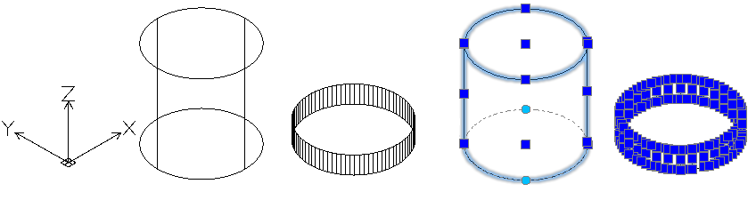
Example:
A cylinder and a circle with thickness
| 3D view of the model | Flattened 3D view |
 |
|
Access
Command: Flatten
Menu: XtraTools > Modify > Flatten
Ribbon: XtraTools > Modify > Flatten
Parent Topic