Modifying Associative Patterns (EditPattern)
Entities within associative patterns retain their relationships. Associative patterns let you edit them in their entirety instead of changing the individual items in the pattern.
You can modify later associative patterns parameters, such as:
The number of columns and rows (within a linear pattern)
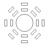
The number of elements (within a circular pattern)
The source element of the pattern
Replace one or more elements in the pattern with specified entities
To make patterns associative, activate the Associative option in the Settings section of the Pattern dialog box.
Use the EditPattern command to modify the shape and appearance of associative patterns.
 You can also edit associative patterns using specific EntityGrips and the Properties palette.
To modify an associativepattern:
Do one of the following:
On the menu, click Modify > Pattern > Edit Pattern.
On the ribbon, click Home > Modify > Edit Pattern.
Type EditPattern.
In the graphics area, specify an associative pattern and press Enter.
The Pattern dialog box opens with the tab that corresponds to the the pattern type you selected (circular or linear).
Specify the corresponding pattern properties.
To modify the source entity of an associative pattern:
Do one of the following:
On the menu, click Modify > Pattern > Edit Pattern.
On the ribbon, click Home > Modify > Edit Pattern.
Type EditPattern.
In the graphics area, specify an associative pattern and press Enter.
The Pattern dialog box opens with the tab that corresponds to the the pattern type you selected (circular or linear).
Under Options, click Edit source
 .
.In the graphics area, click an element of the pattern.
Click OK to access the pattern editing mode.
Modify the source entity as necessary.
Save the changes and click Close (or use the ClosePattern command) to finish editing the pattern source entity.
To replace an element of an associative pattern:
Before starting draw the entities that will replace the elements in the pattern.
Do one of the following:
On the menu, click Modify > Pattern > Edit Pattern.
On the ribbon, click Home > Modify > Edit Pattern.
Type EditPattern.
In the graphics area, specify an associative pattern and press Enter.
The Pattern dialog box opens with the tab that corresponds to the the pattern type you selected (circular or linear).
On the Options panel, click Replace elements
.In the graphics area, specify the replacement entities and press Enter.
Specify the base point for the replacement entities.
Specify pattern elements to be replaced.
Press Enter to finish.
Note: To undo the associativity of patterns, use the Explode command.
Circular Pattern Properties
In the dialog box, Circular tab groups the available properties.
Under Settings, specify the following:
Clockwise. Specifies whether the direction of the circular pattern is clockwise or counterclockwise. The option is available only for associative circular patterns.
Base pattern on. Select an option:
Angle Between and Total Number of Elements
Fill Angle and Angle Between Elements
Fill Angle and Total Number of Elements
Angle between (if required). Specifies the included angle between the base points of the pattern entities and the center of the pattern. Type a positive value or click Pick angle between items
 .
.Fill angle (if required). Type a positive or negative value or click Pick angle to fill
. The default for the angle to fill is 360° - a full circle pattern. A value of zero is not allowed.Total number (if required). Specifies the resulting number of copies in the circular patten (including the source).
Levels. Specifies the number of levels in the 3D circular pattern.
Spacing on levels. Specifies the distance between the levels.
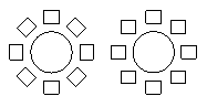
Rows. Specifies the number of rows in the circular pattern.
The following examples shows a circular pattern with two rows, each row has 8 items, fill on 360°.
Spacing on rows. Specifies the distance between the rows within the circular pattern.
Under Element base point, set:
Use last entity selected. Uses the base point from the last entity you specified.
X and Y. Type values or click Pick base point
 to specify the base point in the graphics area.
Under Axis point, for X and Y, type values for the center point of the pattern or click Pick center point
.Select Orient elements about axis to rotate the copies as they are patterned, otherwise they maintain the alignment of the source entities.
Under Options, use the following:
Edit source. Click Select in graphics area
to specify one of the pattern elements as a source entity to modify. Use the ClosePattern command to finish editing the pattern source entities.Replace elements. Replaces the source entities for specified pattern elements or for all elements referencing the original pattern source entities.
Reset. Restores erased pattern elements and removes any element overrides.
Click OK.
Linear Pattern Properties
In the dialog box, click the Linear tab.
Under Settings, specify the following:
For Horizontal axis and Vertical axis, type the number of copies.
For Levels, type the number of levels in the Z direction.
For Spacing between elements on, define spacing between the copies and an angle for the pattern:
Horizontal axis. Specifies the distance between columns. Click Select column offset
 to identify the offset using two points in the drawing. If the column offset is a negative value, columns are added to the left.
Vertical axis. Specifies the distance between rows. Click Select row offset
to identify the offset using two points in the drawing. If the row offset is a negative value, rows are added downward.Levels. Specifies the spacing between levels for 3D pattern.
Pattern angle. Specifies the angle to control how the copies are arranged. Click Select angle
to specify the angle using the pointer.
Under Element base point, set:
Use last entity selected. Uses the base point from the last entity you specified.
X and Y. Type values or click Pick base point
to specify the base point in the graphics area.
Under Options, use the following:
Edit source. Click Select in graphics area
to specify one of the pattern elements as a source entity to modify. Use the ClosePattern command to finish editing the pattern source entities.Replace elements. Replaces the source entities for specified pattern elements or for all elements referencing the original pattern source entities.
Reset. Restores erased pattern elements and removes any element overrides.
Click OK.
Path Pattern Properties
On the Path tab, do the following:
In Settings, specify the path pattern properties:
Associative. Specifies whether the pattern is created associatively or non-associatively.
Base pattern on. Select an option:
Distance Between and Total Number of Elements. Allocates the copies along the path at specified intervals with the specified total number. If the calculated pattern length exceeds the length of the path, the distance between the copies is reduced.
Divide Equally. Allocates the number of copies evenly along the total length of the path.
Measure Equally. Allocates the copies along the path at intervals you specify.
Distance (if required). Specifies the intervals between the copies. Click Specify spacing between elements
to identify the distance in the graphics area.Total number (if required). Specifies the resulting number of pattern copies in the path patten (including the source).
Under Element base point, set:
Use last entity selected. Uses the base point from the last entity you specified.
X and Y. Type values or click Pick base point
to specify the base point in the graphics area.
Under Rows, set:
Count. Specifies the number of rows in the pattern.
Distance. Specifies the distance between the rows. If the distance is a negative value, rows are added downward. Click Specify spacing between elements
to identify the distance in the graphics area.
Under Element alignment, set:
Align elements with path. Aligns each pattern copy to be tangent to the path direction. Otherwise the copied entities maintain the orientation of the source entities.
Specify tangent direction
. Specifies two points in the graphics area which represent the tangency of the copies relative to the path. Use EntitySnaps to refer to the geometry of source entities.Click Remove tangent direction to clear the tangent direction you previously specified.
Angle from tangent. Specifies the rotation angle for the copies relative to the specified tangent direction.
Access
Command: EditPattern
Menu: Modify > Pattern > Edit Pattern
Ribbon: Home > Modify > (Flyout) Edit Pattern
Related Topics
Modifying Associative Pattern