Adding Grid Lines
Grids are auxiliary elements that are useful for placing structural elements, such as columns and walls, in a BIM project.
Grids consist of series of labeled lines. Each grid line consists of the following elements:
- Central line
- Start line
- End line
- Symbols (bubbles)
Use the BIMGridLines command to add grid lines to a BIM drawing.
You can create:
- Vertical grid lines
- Horizontal grid lines
The command automatically numbers each grid line. You can use letters and numbers for labeling grid lines. By default, vertical grid line labels are letters, while horizontal grid line labels are numbers. The numbering starts from the last horizontal, respectively vertical grid line.
Note: Adding grid lines using the Copy command duplicates the grid line without adjusting the numbering.
To add grid lines to a BIM drawing:
Note: You can add grid lines only in horizontal sections.
- Do one of the following:
- On the ribbon, click BIM > Annotate > BIM Grid Lines.
- On the menu, click BIM > Grid Lines.
- Type BIMGridLines.
- In the graphics area, do the following:
- Move the cursor horizontally and specify the points where you want to place vertical grid lines.
Vertical grid lines are automatically alphabetically labeled. The labeling starts from the last vertical grid line label.
- Press Enter to change the grid line direction.
- Move the cursor vertically and specify the points where you want to place horizontal grid lines.
Horizontal grid lines are automatically numbered. The numbering starts from the last horizontal grid line.
- Move the cursor horizontally and specify the points where you want to place vertical grid lines.
- Press Enter.
Customizing Grid Lines
Using the Properties palette you can change the appearance of the grid lines.
You can do the following:
- Hide segments of the grid line. For example, the central segment
- Show or hide grid symbols at grid lines
- Offset grid symbols
- Change the line color, weight, and type. For example, you can use a different color to represent the central segment.
Examples:
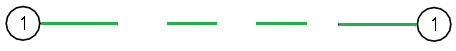
Grid line with gap. Only the end segments are visible.
Grid line with a different line color
Central segment with a different color and type

To show or hide grid symbols:
By default, grid symbols appear at both ends of a grid line.
- In the graphics area, specify a grid line.
- In the Properties palette, in Visibility, specify Yes or No to show or hide the desired grid symbol:
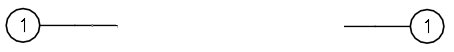
- Start Symbol
- End Symbol
The specified grid line will have symbols at one end.
Adjusting Grid Lines and Symbols Position
Use the middle grip point to move a grid line. In case of overlapping grid symbols, grip points let you offset the bubbles.
To offset a grid symbol:
- In the graphics area, specify a grid line.
The grid line is selected and the grip points are displayed.
- Click and drag the grip point near the grid symbol to move the symbol to the desired location.
Access
Command: BIMGridLines
Menu: BIM > Grid Lines
Ribbon: BIM > Annotate > BIM Grid Lines
Related Topics