Creating Geometric Tolerances
Use the Tolerance command to create and place datum indicators and basic Dimension notations in the drawing.
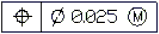
Following is an example of a Tolerance:
Note: You cannot associate Tolerances with drawing entities.
The Properties palette lets you change several display properties of Tolerances, such as:
- Style
- Color of the text and the frame
- Scale
If you select a Tolerance and the ribbon is active, the Tolerance contextual tab appears. The contextual tab groups options and tools for changing Tolerance properties.
The following tables describe the Tolerance and material condition symbols you can select in the Geometric Tolerance dialog box.
Geometric characteristic symbols
| Symbol | Characteristic | Type |
|---|---|---|
 |
Position | Location |
 |
Concentricity or coaxiality | Location |
 |
Symmetry | Location |
 |
Parallelism | Orientation |
 |
Perpendicularity | Orientation |
 |
Angularity | Orientation |
 |
Cylindricity | Form |
 |
Flatness | Form |
 |
Circularity or roundness | Form |
 |
Straightness | Form |
 |
Profile of a surface | Profile |
 |
Profile of a line | Profile |
 |
Circular runout | Runout |
 |
Total runout | Runout |
Material condition symbols
| Symbol | Definition | Type |
|---|---|---|
 |
At maximum material condition, a feature contains the maximum amount of material stated in the limits. | MMC |
 |
At least material condition, a feature contains the minimum amount of material stated in the limits. | LMC |
 |
Regardless of feature size, indicates that the feature can be any size within the stated limits. | RFS |
To create a Tolerance:
- Click Dimension > Tolerance (or type Tolerance).
- In the dialog box, from corresponding lists select symbols for geometric characteristics and material condition (M.C.) specifications. Select Diameter to turn on diameter symbols.
- Complete the specifications by typing tolerance values in the corresponding text boxes.
- Enter datum values as necessary and select appropriate material condition symbols.
- Enter a Datum identifier.
- Enter a Height for the Tolerance.
- Add the Projected tolerance zone symbol if necessary.
- Click OK.
- In the graphics area, specify the position of the Tolerance.
The Tolerance displays in the graphics area.
Access
Command: Tolerance
Menu: Dimension > Tolerance
Ribbon: Annotate > Dimensions > (Flyout) Tolerance 