Flattening Drawings Automatically
Use the Flatten command to automatically flattening drawings.
You can flatten all entities of the drawing or only a specified subset. For example, the SmartSelect command lets you select sets of entities by category. Also, the command may automatically count how many entities of a particular type have been modified during the flattening process.
Note: You can interrupt the execution of the Flatten command at any point by pressing Esc.
Note: After flattening, resulting 2D entities retain their original Layers, LineStyles, and colors.
You can do the following:
Create a 2D representation from a 3D model
When you flatten a 2D view or a 3D view of a 3D model, the command projects the specified 3D entities onto the current viewing plan, or on the XY-plan of the current coordinate system. The model view is created using 2D entities.
Correct drawings that have unknown Z-coordinates
While working on a drawing, it might happen to have properties, such as thickness, elevation or other not representative property for a 2D entity.
 Use one of the following tools to choose a suitable 3D view and check if the drawing has Z-coordinates:
Note: Accuracy loss might occur in the following situations:
Flattening without hidden lines
Flattening a perspective view
Properties that may add elevation or Z coordinate to a 2D entity:
Entity |
Properties |
|---|---|
Polyline, Hatch, Cloud |
Elevation |
Line |
Start Z, End Z |
Circle, Arc, Ellipse |
Center Z |
Spline |
Fit Point Z |
Annotative Entities |
Position Z |
To flatten a drawing with unknown Z coordinates:
Do one of the following:
On the menu, click XtraTools > Modify > Flatten.
On the ribbon, click XtraTools > Modify > Flatten.
Type Flatten.
Optionally, specify Statistics.
Type Yes or No to enable or disable the report on modified entities.
Optionally, specify Plane to set the projection plane.
Specify XY to flatten entities on the XY-plane.
Select all entities of the drawing with Z coordinate different than 0.
Alternatively, you can use the SmartSelect command to select the entities with varying Z-coordinates.
Press Enter.
To specify whether to remove hidden lines, type Yes or No.
The drawing is flattened. All Z coordinates are 0.
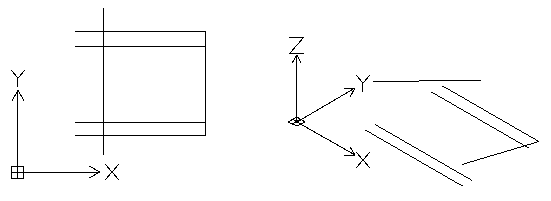
Example:
Top view of a seemingly 2D drawing |
3D view shows entities with Z coordinate |
|
|
Flattened top view |
3D view shows that all entities are in the same plane |
|
|

To flatten a 3D view of a model:
In the graphics area, set up a suitable 3D view. Use the Views command.
Do one of the following:
On the menu, click XtraTools > Modify > Flatten.
On the ribbon, click XtraTools > Modify > Flatten.
Type Flatten.
Optionally, specify Statistics.
Type Yes or No to enable or disable the report on modified entities.
Optionally, specify Plane to set the projection plane.
Specify View to flatten entities onto the current view plane.
Select all entities of the drawing.
Alternatively, you can use the SmartSelect command to select the entities to flatten.Press Enter.
To specify whether to remove hidden lines, type Yes or No.
The 3D view is flattened onto the current viewing plane. The 2D representation is created using 2D entities.
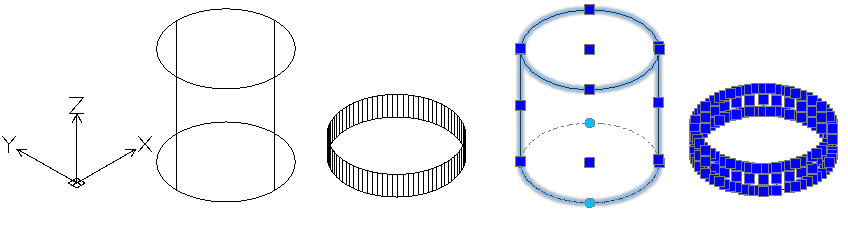
Example:
A cylinder and a circle with thickness
3D view of the model |
Flattened 3D view |
|
|
Access
Command: Flatten
Menu: XtraTools > Modify > Flatten
Ribbon: XtraTools > Modify > Flatten
Parent Topic