Adding Feature Control Frames
The AM_FeatureControlFrame command creates a feature control frame which you can attach to an entity in the drawing.
A feature control frame is a rectangular symbol used for displaying the conditions and tolerances of a geometric control on a part’s feature.
The command offers various geometric dimensioning and tolerancing symbols (GD&T) to specify geometric tolerances with feature control frames.
The feature control frame consists of the following elements:
GD & T symbol
Leaders
Surface extension lines
Surface indication leaders
Elements of a feature control frame
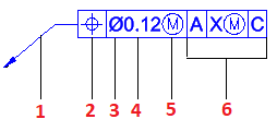
Leader arrow
Geometric characteristic symbol
Diameter symbol
Tolerance
Modifier for the tolerance
Datum
To create a feature control frame:
Type AM_FeatureControlFrame.
In the graphics area, specify an entity to attach the symbol to.
Specify a point to define the leader.
Specify one or more points to define the vertices of the leader and press Enter.
The first leader segment is vertical or horizontal. To override this restriction, press Shift + F as you move the mouse pointer.
In the Feature Control Frame dialog box do the necessary settings.
Click OK.
Contents
Editing Feature Control Frames
Use the AM_FeatureControlFrameEdit command to modify feature control frames properties.
Feature Control Frame Dialog Box
Use the Feature Control Frame dialog box to configure feature control frames which you can attach to entities in the drawing.