Adding Surface Finish Symbols
Surface finishes depend on the manufacturing procedure used to produce them.
Surface finish consists of the following elements:
Roughness. Small irregularities in the surface geometry.
Lay. Lay is the dominant pattern produced by the manufacturing process and the orientation of that pattern.
Parallel
Perpendicular
Circular
Crosshatched
Radial
Multi-directional
Particulate
Waviness. Waviness is the most broadly spaced surface finish variations that are not considered flatness defects.
Cutoff. Defines the wavelengths to include in the calculation of surface texture parameters.
Surface finish symbols specify description of surface, such as surface texture, surface imperfections, material add-ons. In technical drawings standards, the surface finish symbol is represented using the root symbol.
Use the AM_SurfaceSymbol command to add standard-based surface finish symbols to your drawing. You can place a surface finish symbol at a specified location or attach it to an existing entity. When you attach the symbol to an entity, the software automatically manages the connection between the symbol and the entity. The symbol moves along with the entity.
Along with the surface finish symbol, you can create surface indication leaders.
At any time, you can modify an existing surface finish symbol properties using the AM_SurfaceSymbolEdit command.
In the Surface Finish dialog box, you can customize the symbol to suit your drafting requirements.
Change the appearance of the symbol
Customize text and leader settings
Appearance of the all around sign
Note: Default settings match the drafting standard.
Elements of a surface finish symbol
The basic surface finish symbol is a check mark pointing to the surface to be specified. Variations of the checkmark provide additional information.
The symbol must display, at least, the name of the specified parameter and the corresponding limit value. It is possible to place additional information around the root symbol, which varies according to the drafting standard.
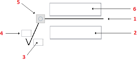
Root symbol
Specification string
Orientation of texture (lay)
Material removal indication
All around sign
Additional information to express constraints on material or machining
Supported Drafting Standards
Standard / Revision |
Surface Extension Lines |
Surface Indication Leaders |
Majority Symbol |
|---|---|---|---|
ASME Y14.36M (1996) |
Yes |
||
BS EN ISO 1302 (2002) |
Yes |
||
BS 308 (1990) |
Yes |
||
DIN EN ISO 1302 (2002) |
Yes |
Yes |
Yes |
DIN ISO 1302 (1992) |
Yes |
Yes |
|
GB/T 131 (1993) |
Yes |
Yes |
|
ISO 1302 (2002(E)) |
Yes |
Yes |
Yes |
ISO 1302 (1978) |
Yes |
Yes |
|
JIS B 0031 (2003) |
Yes |
Yes |
Yes |
JIS B 0031 (1994) |
Yes |
Yes |
To attach a surface finish symbol to an entity:
Do one of the following:
On the menu, click Mechanical Annotate > Symbols > Surface Finish > Create
On the ribbon, select Mechanical Annotate > Symbols > Surface Finish > Create
.
Type AM_SurfaceSymbol.
In the drawing area, specify an entity to attach the surface finish symbol to.
Specify one or more points to define the vertices of the leader and press Enter.
On the Symbol tab, specify the requirements according to the standard:
Set the symbol type
Add a tail
Majority
All around
Click OK.
Contents
Editing Surface Finish Symbols
Use the AM_SurfaceSymbolEdit command to configure the surface finish symbols you add to drawings.
Surface Finish Symbols Dialog Box
Use the Surface Finish Symbol dialog box to configure the surface finish symbols from the drawings.