Welding Dialog Box
Use the Welding dialog box to specify the default settings of the welding symbols for the current drafting standard.
You can configure requirements for weldings to meet specifications and use of welding symbols on technical drawings.
As you configure the properties, the welding symbol on the drawing area changes in real time.
Standard
Displays the name of the active standard.
Revision
Displays the most recent revision of the standard the symbol complies with.
The dialog box contains the following tabs:
Symbol Tab
Lets you configure the welding requirements to display in a welding symbol.
Options
Lets you specify the symbol type.
Flip sides |
Swaps the symbols on the arrow side with symbols on the opposite side. |
Flip Symbol |
Flips the symbol so that the weld tail is placed to the left of the arrow. |
Stagger |
Indicates an intermittent weld that requires a sequence of welds on each side of the joint that do not line up evenly with each other. This option is only available when the Symbol type is Fillet and Display is set to Both sides. |
Mirror |
Indicates that the weld represents a staggered intermittent weld, where the shape and dimensions of the fillet are equal on both sides. This option is only available if you select JIS fillet welds for both sides. |
Spacer |
Adds a spacer symbol to the weld. This option is available for the following standards and symbol types:
|
|
Adds a reference line to the welding symbol to indicate a sequence of welding operations. |
|
Deletes the current reference line. |
|
Selects the next reference line closest to the arrow and displays its settings in the dialog box. |
|
Selects the next reference line futhest from the arrow and displays its settings in the dialog box. |
Requirements
Lets you specify welding parameters. You can modify different fields based on the selected weld type. Editing fields location in relation with the symbol shows the proper location for each parameter.
When you move the mouse cursor over an editing field, a tooltip describes what information should you specify in that field.
Weld type |
Specifies the weld type for the current process. |
Field Weld |
Adds the field weld to the symbol. |
All around |
Adds the all around sign to the symbol. |
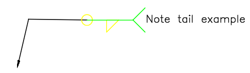
Note tail |
Adds the reference line tail to the symbol. |
Examples:
All around and note tail symbols on a welding symbol
Clear
Clears all the data and restores the default values.
Leader and Text Tab
Groups the option for configuring leaders and text.
Leader
Arrowhead |
Specifies the default leader arrowhead type for welding symbols. Specifying By Standard lets you use the arrowhead from the current drafting standard. When you change the arrowhead specified for the current drafting standard in the Standard Settings dialog box, the arrowhead of the welding symbol automatically updates. |
Edit leader segments |
Groups options for adding and removing leaders, leader segments, and leader nodes. |
Edit entity attachment |
Attaches or detaches the symbol to an object in the drawing. |
Text
Text justification |
Sets the text justification to left, center, or right. |
Weld Settings Dialog Box
Opens the Welding Settings dialog box, where you can specify the default settings for the welding symbol.
Revision
Displays the most recent revision of the standard the symbol complies with.
Symbol filter |
Lets you specify which symbols will be available for insertion in welding symbols.
|
Leader |
|
Text |
Lets you specify the default text height and line color for the symbol from the feature control frame. |
Restore Defaults
Restores all values from the drafting standard.
Access
Command: AM_WeldingSymbol
Menu: Mechanical Annotate > Symbols > Welding > Create
Ribbon: Mechanical Annotate > Symbols > Welding > Create
Parent Topic