Creating Section Lines
Section views let you reveal interior parts when hidden lines cannot represent them. A cutting plane through the model creates a cross section.
Use the AM_SectionLine command to draw section lines. A section line indicates where the cutting plane cuts the model. You can create multiple sections on an entity.
You can create section lines for the following types of section views:
Full section. The cutting plane runs through the entire length of the sectioned entity.
Aligned section. Two non parallel cutting plane run through the part being sectioned.
Half section. The cutting plane runs through a portion of the part being sectioned.
Offset section. Includes in a section features of an entity that are not in a straight line. The cutting plane is bent to run through the features of the entity.
Examples
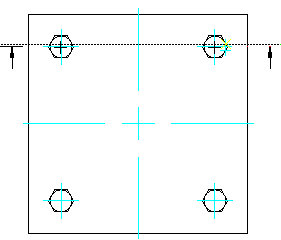
Full section
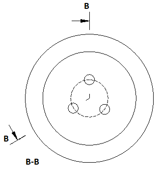
Aligned section
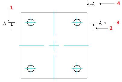
The command creates the following entities:
Section line
Direction arrow
Section view identifier
Section view label
The command lets you control the appearance of different entities of the section line, such as arrows, lines, and name.
To create a section line:
Do one of the following:
On the ribbon, select Mechanical Content > Details > Section Line > Create.
On the menu, click Mechanical Content > Details > Section Line > Create.
Type AM_SectionLine.
In the graphics area, specify the start point of the section line.
Specify the next points of the section line and press Enter.
Specify a letter to reference the section line at the start point and press Enter.
Move the mouse cursor to specify the side of the cutting plane.
Specify the insertion point for the section line label.
To create an aligned section line:
Do one of the following:
On the ribbon, select Mechanical Content > Details > Section Line > Create.
On the menu, click Mechanical Content > Details > Section Line > Create.
Type AM_SectionLine.
In the graphics area, specify the start point of the section line.
Specify the Center option and press Enter.
In the graphics area, specify the center of the cylindrical entity.
Specify two points to define the angle.
Specify a letter to reference the section line at the start point and press Enter.
Move the mouse cursor to specify the side of the cutting plane.
Specify the insertion point for the section line label.
To create a section line for a half section view:
Do one of the following:
On the ribbon, select Mechanical Content > Details > Section Line > Create.
On the menu, click Mechanical Content > Details > Section Line > Create.
Type AM_SectionLine.
In the graphics area, specify the start point of the section line.
Specify the next point of the section line.
Specify the Half option and press Enter.
Specify a letter to reference the section line at the start point and press Enter.
Move the mouse cursor to specify the side of the cutting plane.
Specify the insertion point for the section line label.
To specify the elements to display with the section line:
Do one of the following:
On the ribbon, select Mechanical Content > Details > Section Line > Create.
On the menu, click Mechanical Content > Details > Section Line > Create.
Type AM_SectionLine.
Optionally, type Visibility to specify the entities to display with the section line. The following options are available:
Arrow. Shows or hides the direction arrows on the section line.
Line. Specifies how to draw section line segments:
Betweenplanes. Draws section line segments using the line type specified in the Entity Property Settings dialog box.
Continuous. Draws section line segments using the same line type as the ends.
None. Does not draw section line segments.
Name. Shows or hides the section line labels.
Planenames. Shows or hides the identifiers on the section line vertices.
In the graphics area, draw the section line.
Access
Command: AM_SectionLine
Menu: Mechanical Content > Details > Section Line > Create
Ribbon: Mechanical Content > Details > Section Line > Create
Related Topics
Parent Topic