Adding Tolerances and Fits to Dimensions
In mechanical engineering, tolerances are used on production drawings to control the parts, as the final dimensions of a part may vary from the stated measurements. For example, a 500 mm bar on a drawing may end up 501 mm as cut part from a bar.
Tolerances apply to linear, angular, circular, and other physical dimensions.
Dimensioning a drawing means also to identify the tolerance required for each dimension. Tolerance is the amount a particular dimension is allowed to vary. Every dimension must have an associated tolerance, which must appear on the dimension on the drawing.
You can include a tolerance value to any dimension, with the minimum and maximum acceptable limit.
The tolerance is the difference between the minimum and maximum limit. For example, if a bar or a pipe accepts length variation between 1000 mm and 1003 mm, the tolerance is 3 mm, in this case.
The Power Dimensioning contextual ribbon groups tools for adding fit and tolerances to the dimensions. Various representations are available for fits, as well as for tolerances.
Fits
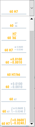
On the Fit panel, the Representation drop-down list shows available fit representations.
Once you select the desired fit representation, you can specify the fit notation and number in the Fit dialog box.
Tolerances
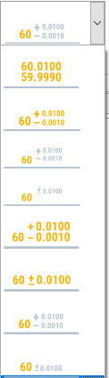
The Method drop-down list contains thumbnails that illustrate available tolerance methods.
Once you select the desired method, you can specify the upper and lower limit.
You can also control the precision of fits and tolerances, independently of the precision of the dimension value. The drafting standard controls text sizes for the deviation automatically.
To add tolerances to dimensions:
In the graphics area, select the dimension to edit.
Click Power Dimensioning > Tolerance > Tolerance.
In Method, select the thumbnail that shows the desired tolerance representation.
Enter a value for the upper and lower limit.
To add fits to dimensions:
In the graphics area, select the dimension to edit.
Click Power Dimensioning > Fit > Fit.
In Representation, select the thumbnail that shows the desired fit representation.
If necessary, in Symbol, select Fit dialog box.
In the Fit dialog box you can select a fit symbol for the specified dimension.
To modify the precision of a fit or tolerance:
In the graphics area, select the dimension to edit.
On the Power Dimensioning contextual ribbon, on the Precision panel, do the following:
In Primary: To modify the precision of the tolerance of primary units, specify the number of digits to round off to.
In Alternate: To modify the precision of the tolerance of alternate units, specify the number of digits to round off to.
Parent Topic